Home avatar

Deokgon Kim

Esp8266 Rc522

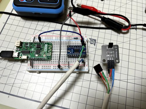
Tested ESP8266 with RC522 NFC/RFID Reader

RC522 is NFC/RFID reader, and it can be integrated into ESPHOME

  • esphome configuration

    # Example configuration entry
    http_request:
    
    output:
    - platform: esp8266_pwm
      pin: 5
      id: my_buzzer
    
    rtttl:
      output: my_buzzer
      gain: 0.1
    
    spi:
      clk_pin: 14
      mosi_pin: 13
      miso_pin: 12
    
    rc522_spi:
      cs_pin: 15
      on_tag:
        then:
          - http_request.send:
              method: POST
              url: !secret nfc_tag_call_url
              verify_ssl: false
              headers:
                Content-Type: application/json
              json:
                tag: !lambda
                  return x;
          - rtttl.play:
              # rtttl: 'siren:d=8,o=5,b=100:d,e,d,e,d,e,d,e'
              rtttl: 'two_short:d=4,o=5,b=100:16e6,16e6'
    
    binary_sensor:
      - platform: rc522
        uid: !secret my_room_card
        name: "My Room Card"
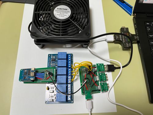
  • Two separate function

2023 Beelink Mini S

I wasn’t satisfied by Pico PC so,

I bought another mini PC. the Beelink Mini S

Here are some specs.

  • CPU : Intel N95
  • Memory : 8GB
  • SSD : 256GB
  • Display Output : HDMI x 2
  • USB : USB-A x 4
  • Ethernet : 1 GbE x 1
  • Wifi : Wifi 5

Better than Pico PC

  • Silent : most important Pico PC doesn’t include PWM controlled FAN. (what I mostly disappointed about Pico PC)
  • Slightly faster. N95 is slightly faster than J series

Weaknesses?

2023 Esp8266 Ir Remote

When I was using raspberry pi, I bought a IR transceiver module for Arduino. and used it for several years. IR transceiver

Raspberyr Pi, IR Transceiver and DHT11

And this year, I am interested in ESP8266, so I bought another IR receiver, IR transmitter.

Install esp8266 and voltage converter on breadboard.

esp8266, breadboard, and ir receiver

Install IR receiver and IR transmitter in front of tv

Raspberry Pi 1

  • Bought : â‚©58,000 2013/04/24

    • with : PiFace, BOARD, I/O EXPANSION, RASPBERRY-PI (â‚©48,570)
  • At First : install raspbian. tested relay, and tested led on PiFace

  • As a IR Remote controller : telegram-bot-try2, 2019 May IoT project

  • As a Thermal sensor : finally just read DHT11 temperature/humidity and send it to the server.

    #!/bin/bash
    
    export API_URL=https://public-api.dgkim.net
    export API_KEY=----
    
    export DHT11=/home/pi/git/rpi_sensor/src/test_dht11
    
    export HUMI_TEMP=$($DHT11 | tail -1)
    
    HUMI=$(echo $HUMI_TEMP | tr "," "\n" | head -1)
    TEMP=$(echo $HUMI_TEMP | tr "," "\n" | tail -1)
    
    TIMESTAMP=$(date +"%Y-%m-%dT%H:%M:%S%z")
    
    echo "HUMI $HUMI"
    echo "TEMP $TEMP"
    
    
    curl -X POST "$API_URL/v1/temperatures/" \
    -H 'Content-Type: application/json' \
    -H "X-API-KEY: $API_KEY" \
    -d"
    {
      \"temperature\": $TEMP
    }
    "
  • Today : Turn it off.. and remove SD Card from it. Please Rest in Peace my raspberry pi.

Esphome PIR Sensor + LED Strip

Story

I wanted to implement automatic LED light, when I approach kitchen.

  • ESP8266 compatible board. (I use ESP01 board this time)
  • WS2812B LED Strip (5v addressable LED)
  • HC-SR501 PIR Sensor (body detection sensor)
  • WS2812B

    • vcc : to USB 5v positive pin
    • gnd : to USB ground pin
    • data : to GPIO1 of ESP01
  • HC-SR501

    • vcc : to USB 5v positive or 3.3v
    • gnd : to USB ground pin
    • data : to GPIO0 of ESP01

Overall Photo

Esphome Relay Fan

ESPHOME + Relay + FAN

Overall Photo

ESP8266 PCB

esphome:
  name: six

esp8266:
  board: d1_mini

# Enable logging
logger:

# Enable Home Assistant API
api:
  password: ""

ota:
  password: ""

wifi:
  ssid: !secret wifi_ssid
  password: !secret wifi_password

  # Enable fallback hotspot (captive portal) in case wifi connection fails
  ap:
    ssid: !secret wifi_fb_ssid
    password: !secret wifi_fb_password

captive_portal:
    
# Example configuration entry
switch:
  - platform: gpio
    pin: GPIO4
    name: "Switch2"
    inverted: true
  - platform: gpio
    pin: GPIO5
    name: "Switch3"
    inverted: true
  - platform: gpio
    pin: GPIO12
    name: "Switch4"
    inverted: true
  - platform: gpio
    pin: GPIO13
    name: "Switch5"
    inverted: true
  - platform: gpio
    pin: GPIO14
    name: "Switch6"
    inverted: true
  • Turn on when RPi4’s temperature is above 58
alias: rpi4-cooling
description: ""
trigger:
  - platform: numeric_state
    entity_id: sensor.rpi4_temperature
    above: 58
condition: []
action:
  - type: turn_on
    device_id: 98f3c834a50732c3b8981d0d5925158a
    entity_id: 186a943f4f7f486e95ce2bb1c6751a7f
    domain: switch
mode: single
  • Turn off when RPi4’s temperature is below 50
alias: rpi4-cooling-stop
description: ""
trigger:
  - platform: numeric_state
    entity_id: sensor.rpi4_temperature
    below: 50
condition: []
action:
  - type: turn_off
    device_id: 98f3c834a50732c3b8981d0d5925158a
    entity_id: 186a943f4f7f486e95ce2bb1c6751a7f
    domain: switch
mode: single